This paper describes the function and operation of lubrication systems for Ball Mill and SAG Mill Drives. Provided within this paper are hydraulic schematics, functional description and a general overview of system layout as well as some of the important features and factors relevant to improving the reliability of this very critical part of the grinding mill drive system. Also discussed are ...
WhatsApp: +86 18838072829
A fluid coupling converts power from the drive shaft into velocity energy of oil, and uses this energy to transmit the power to the driven shaft; as Figure 2 shows, it may be considered to be a combination of a pump and a turbine efficiently housed in a casing. ... When the drive shaft turns, the impeller functions as a pump, giving ...
WhatsApp: +86 18838072829
High temperature of the ball mill will affact the efficiency. 3 For every 1% increase in moisture, the output of the ball mill will be reduced by 8% 10%. 4 when the moisture is greater than 5%, the ball mill will be unable to perform the grinding operation. 5. The bearing of the ball mill is overheated and the motor is overloaded.
WhatsApp: +86 18838072829
Ball Mill Sole Plate. This crown should be between .002″ and . 003″, per foot of length of sole plate. For example, if the sole plate is about 8′ long, the crown should be between .016″ and .024″. Ball Mill Sole Plate. After all shimming is completed, the sole plate and bases should be grouted in position.
WhatsApp: +86 18838072829
lifetime of electric motors. Also at startup, a fluid coupling allows more torque to pass to the load for acceleration than in drive systems without a fluid coupling. Figure 3 shows two curves for a single fluid coupling and a characteristic curve of an electric motor. It is obvious from the stall curve of the fluid coupling (s = ) and the ...
WhatsApp: +86 18838072829
Hydraulic quick couplings. Hydraulic quick couplings allow the connection and disconnection of fluid lines in a fast and convenient way. They provide the users the ability to rapidly connect and disconnect hydraulic hoses to machines or attachments. All quick couplers have two parts: the male half and the half.
WhatsApp: +86 18838072829
Fluid Coupling allow the Motor to run quickly upto the speed, where its overload capacity may be used for starting the machine. Pembril PSS Fluid Couplings are installed between coaxial shaft. Normally PSS Fluid Coupling is mounted between the motor and machine shaft and connected by flexible couplings, which absorb the small assembly ...
WhatsApp: +86 18838072829
customised coupling products. SKF Couplings cover a wide range of coupling types, sizes and capacity ratings for many applications and factory environments. For large, heavy duty applications, SKF has large size couplings. These couplings, which provide optimum contact with the shaft, can accommodate high torque values,
WhatsApp: +86 18838072829
Accelerate your toughest particle simulations by using the most powerful DEM software in the market. Ansys Rocky contains industry leading features and capabilities to solve large, complex problems accurately and efficiently. MultiGPU Processing. Accurate Particle Physics. Automation and Customization. CFD Coupling. Surface Wear. 3D Scan Import.
WhatsApp: +86 18838072829
However, for availability the mean time to repair (MTTR) is equally important. Still, to be fair, the MTBF of a fluid coupling is in the range 25 to 40 years and therefore higher than the MTBF of a VFD with 8 to 12 years. However, a repair of VFD usually consists of a replacement of faulty component.
WhatsApp: +86 18838072829
Main Parts. 1. Housing: It is also known as the shell. It has oiltight seal around the drive shaft. It also protects the impeller and turbine from outside damage. 2. Impeller or pump: It is a turbine which is connected to the input shaft and called as impeller.
WhatsApp: +86 18838072829
Schematic diagram of the drive system allowing the use of a fluid coupling for mill startup: 1asynchronous motor 630 kW 1000 RPM, 2fluid coupling, 3gearbox, 4ball mill.
WhatsApp: +86 18838072829
A rotary union is a union that allows for rotation of the united parts. It is thus a device that provides a seal between a stationary supply passage (such as pipe or tubing) and a rotating part (such as a drum, cylinder, or spindle) to permit the flow of a fluid into and/or out of the rotating part.
WhatsApp: +86 18838072829
The fluid coupling also known as the hydraulic coupling is a hydrodynamic device that is used to transfer rotational power from one shaft to another by the use of transmission fluid comprised of three main elements: Driving impeller mounted on the input shaft. Driven impeller mounted on the output shaft. Cover, flanged to the output impeller ...
WhatsApp: +86 18838072829
offset, and axial. In addition to these primary functions, flexible couplings can also be required to dampen vibration, reduce peak or shock loads, protect the equipment from overload, or measure the output torque from the driven equipment, in addition to a number of other functions. General Purpose General purpose couplings are used in lower speed
WhatsApp: +86 18838072829
function of fluid coupling in ball mill function of membrane coupling for cement mill. Membrane Topological Analysis of the ProtonCoupled Folate, function of membrane coupling for cement mill,3 Mar 2010 ...
WhatsApp: +86 18838072829
The acceleration factor of the ball or rod mass is a function of the peripheral speed of the mill. Thus. P = f4(F) = f1(D²)·f5(υ) ... The Sullivan rod mill with its fluid drive coupling has made this test possible, a test out of the reach of practically all other grinding installations. This may be why the relationship between mill capacity ...
WhatsApp: +86 18838072829
By mill we refer to Ball Mills, Rod Mills and SAG Mills. ... To protect the motors from damage, clutches, torque convertors or fluid couplings have been added to some drive lines. An air clutch allows the motor to be brought up to full rpm before the load is put onto it. Once the clutch has been engaged it gives a certain amount of slippage to ...
WhatsApp: +86 18838072829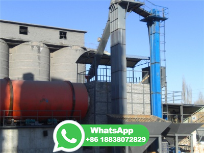
The grinding process of the ball mill is an essential operation in metallurgical concentration plants. Generally, the model of the process is established as a multivariable system characterized with strong coupling and time delay. In previous research, a twoinputtwooutput model was applied to describe the system, in which some key indicators of the process were ignored. To this end, a three ...
WhatsApp: +86 18838072829
The fast yacht Dying Swan complex failure. Clifford Matthews BSc (Hons), CEng, MBA, in Case Studies in Engineering Design, 1998. GT drive train alignment. The output shaft is connected to the input pinion shaft of the gearbox by a 'high speed' coupling shaft. This has flexible diaphragm elements and so allows some lateral misalignment between the GT and gearbox but, more importantly ...
WhatsApp: +86 18838072829
A fluid coupling or hydraulic coupling is a hydrodynamic or hydrokinetic equipment that can transmit power and torque with the help of liquid (hydraulic oil). It belongs to the category of flexible coupling power transmission. This is based on hydrodynamic torque transmission device. It is the assembly of pump impeller, casing gaskets ...
WhatsApp: +86 18838072829
The details of the ball mill motor are as follows. Power = kW or HP and the speed is 343 rpm. Load calculations (prior to failure analysis) The ball mill can experience failure based on the maximum normal stress theory as the working loads acting in the ball mill is concentrated across the seam of the mill periphery.
WhatsApp: +86 18838072829
The dynamics of tumbling mills and the energy efficiency analysis of copper ore ball mill drive systems are represented in [21]. Modern systems of condition monitoring can include such useful ...
WhatsApp: +86 18838072829
Energy Efficiency Analysis of Copper Ore Ball Mill Drive ... Schematic diagram of the drive system allowing the use of a fluid coupling for mill startup: 1—asynchronous motor 630 kW 1000 RPM, 2—fluid coupling, 3—gearbox, 4—ball mill. Figure 9. Dynamic simulation of the ball mill startup process with the use of the TVV 866 fluid coupling.
WhatsApp: +86 18838072829
Soft and safe. Hydrodynamic fluid coupling; Nominal output from kW up to 2,500 kW with 15 sizes; Temperature range: from 40 °C to +50 °C Especially within tough applications, drive components and processing machines are subject to extreme ® couplings limit start and maximum torque within the drive train and serve as starting aids for the motor and as overload protection ...
WhatsApp: +86 18838072829
1. Rigid coupling. 2. Flexible couplings. 1. Rigid coupling. It is used to connect two shafts, which are in perfect alignment. It consists of two flanges with hubs, one keyed to the driving shaft and other two the driven shaft. Two flanges are bolted together.
WhatsApp: +86 18838072829
Fluid coupling is a hydrodynamic device which is used to transfer rotational power from one shaft to another by the use of transmission fluid. Types: There are two types of fluid coupling normally.
WhatsApp: +86 18838072829
Fluid coupling memiliki cara kerja sederhana. Memanfaatkan 4 komponen dasar, impeller, housing, turbine, dan output shaft, fluid coupling menghasilkan tenaga dan menyerahkan nya ke bagian transmission. Prosesnya dimulai dari housing. Terdapat turbin dan impeller yang terpasang dalam housing sebagai tempat oli berkumpul.
WhatsApp: +86 18838072829
A material supplier from Belgium would like to produce limestone powder for his custome...

India is rich in various mineral resources and it is an important mineral processing market
Copyright © 2023 GMC Co., Ltd. SiteMap

